| Description | Value |
| Rated line / phase supply voltage, V | 400 / 230, 415 / 240 |
| Mains frequency, Hz | 45 – 65 |
| Harmonic composition (unsinusoidality) of supply voltage | EN 50160 |
| Control range of response threshold for Umax/Umin, as a percentage of rated voltage | 5 – 50 |
| Control range of protection operation time, s | 0 – 10 |
| Control range of AR time, s | 0 – 600 |
| Fixed delay of minimum voltage response, s | 12* |
| Response time when one phase breaks, max., s | 0.2 |
| Readiness time when power supply voltage is supplied, max., s | 0.2** |
| Phase imbalance determination value, V | 30 |
| Hysteresis of voltage, V | 5 – 6 |
| Hysteresis of phase imbalance, V | 5 – 6 |
| Accuracy of determination of the voltage operation threshold, max., V | 3 |
| Voltage when maintaining serviceability: – for one phase, V – for three phases, V | 95 – 450 95 – 450 |
| Power consumption (when load is connected), max., W | 1.2 |
| Maximum switching current of output contacts, A | 5 |
| Commutation life of output contacts: – under load of 5 А (cos φ = 1.0), min., time – under load of 1 А (cos φ = 1.0), min., time | 100 thousand 1 million |
| Device service | Switchgear and controlgear |
| Rated operating condition | Continuous |
| Protection class rating of the front panel | IP40 |
| Protection class rating of the terminal block | IP20 |
| Electric shock protection class | II |
| Climatic design version | NC 3.1 |
| Permissible contamination level | II |
| Overvoltage category | III |
| Rated voltage of insulation, V | 450 |
| Rated impulse withstand voltage, kV | 4.0 |
| Conductor cross-section for connecting to terminals, mm² | 0.5-1.5 |
| Tightening torque of the terminal screws, N*m | 0.4 |
| Weight, max., kg | 0.100 |
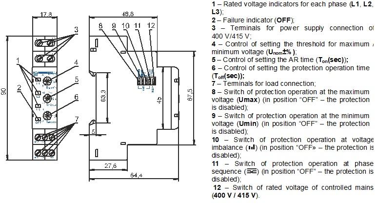
| Overall dimensions (Fig. 1), H*B*L, mm | 90*17.8*64.4 |
| The device installation (mounting) is on standard 35 mm DIN-rail. |
| The device remains operational capability in any position in space. |
Housing material – self-extinguishing plastic | |
Notes: * – When the input voltage drops below Umin, the fixed operation time of the device is 12 seconds, if the switches Umax and Umin are in the “ON” position. With any other combination of switches Umax and Umin, the device will operate after the delay time set by the User with Тoff(sec) control. If during this time (12 seconds) the mains parameters change, for example, at the maximum voltage, the device will operate at the smallest of the periods – after the delay time specified by the User, or after the time remaining of 12 seconds. ** – When working in “Maximum Voltage Control” mode, the ready time is 0.3 seconds. | |


