
UBZ-304 Numeric electric motor protection device is designed for protection of asynchronous LT motors having power of 2.5 to 315 kW (5A – 630A), with use of external standard current transformers having output current of 5 amperes (secondary), works in power mains with isolated neural or with solidly grounded neutral terminals.
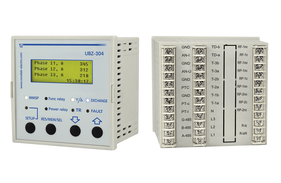
The device provides continuous monitoring of the mains voltage parameters and RMS phase/line currents of the three-phase electric equipment of 380V-415V 50Hz, as well as for the motor insulation resistance test. More than 90 parameters can be programmed/customised depending on application & usage with variable trip delay and auto-reset delays. Four line full function backlit LCD display provides all information and eases programming from front panel. Built In RS-232 & RS-485 Modbus communication for DCS/ SCADA integration, realtime monitoring, programming and remote control. Device comes with free PC software for realtime monitoring & programming. Universally accepted flush mounted 96 x 96 x 78.3mm overall dimensions.
UBZ performs the following protection types for electric motors:
- over-current protection in phases;
- ground fault protection (zero-sequence current);
- phase current asymmetry (negative-sequence current);
- for exceeding negative-sequence current factor to negative-sequence voltage factor;
- thermal overload;
- undercurrent protection in phases (dry-run);
- delayed starting (rotor blocking);
- overheating of windings (RTD inputs);
- minimum line voltage;
- maximum line voltage;
- line voltage imbalance (negative sequence voltage protection);
- improper phase sequence;
- decreasing of mains frequency lower that setting;
- for increasing of mains frequency higher that setting;
- minimum insulation resistance of the motor winding;
- motor phase loss (protection is operated when the motor current is disabled in one (two) phase).
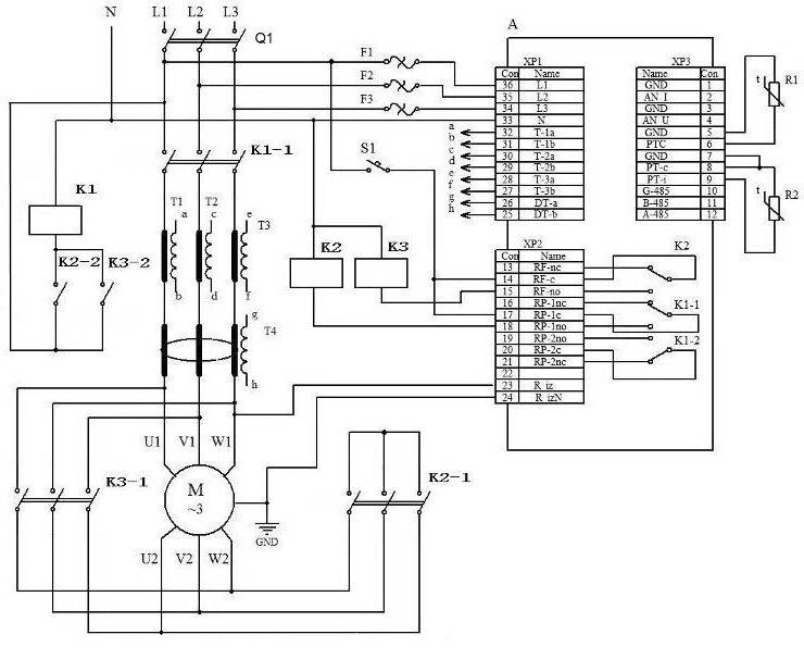
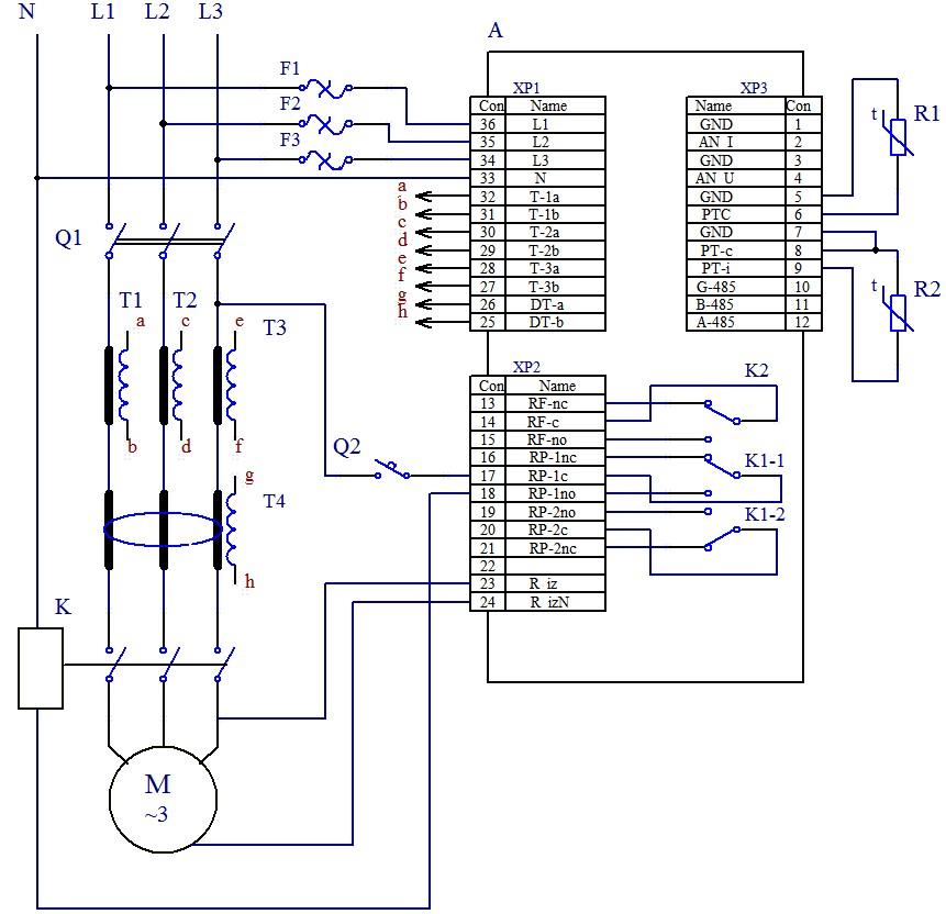
For each type of protection, it is possible to permit and prohibit the load automatic reset. The unit provides for electric equipment protection by means of a magnetic starter (contactor) coil control.
The unit determines load currents when the load relay is open with the open load and programmable relays in the star-delta mode). In this case, the unit shall indicate the fault of an external contactor, which is starting the motor until unit deactivation.
Communication:
- control and parameters transfer via RS-485 interface according to MODBUS/ASCII protocol
- control and parameters transfer via RS-232 interface
Additional Information:
- Item Code: UBZ-304
- Port of Dispatch: New Delhi, India
Technical Specifications | Value |
Operating supply voltage, three-phase | 415 V, 50 Hz |
Mains frequency, Hz | 48-62 |
Rated current of CT, A | 5 |
(Phase/line) voltage hysteresis, V | 10/17 |
Heat hysteresis, in % of accumulated heat in case of shutdown | 33 |
Determination accuracy of trip threshold for current, not more, in % of rated value | 2 |
Determination accuracy of trip threshold for voltage, not more, V | 3 |
Determination accuracy of out-of-phase voltage, not more, V | 3 |
Voltage when maintaining serviceability: – phase voltage, when powered by one phase and zero wire is connected, not less, V – line voltage, when powered by three phases, not more, V |
180 450 |
Analog inputs: – input to connect temperature transmitter (types: Pt100, Ni100, Ni120), pc.; – input to connect temperature transmitter of PTC-1000 type, pc.; – three analog inputs for standard CT with 5A output (T-0.66 type or similar), pc.; – input to connect differential current transformer (zero sequence transformer) pc.; – input to measure current of 0-20 mA, pc.; – input to measure voltage of 0–10 V, pc.. |
1 1 3 1 1 1 |
Main outputs: – load relay – two groups of changeover contacts to control the electric motor starter – 8 A, 250 V at cos φ=1; – functional relay – one group of changeover contacts – 16A, 250V at cos φ=1 (function of the relay is set by the user). |
|
Permit according to temperature of temperature transmitters, °С | 1 |
Power consumption (under load), VA, not more | 5.0 |
Weight, not more, kg | 0.34 |
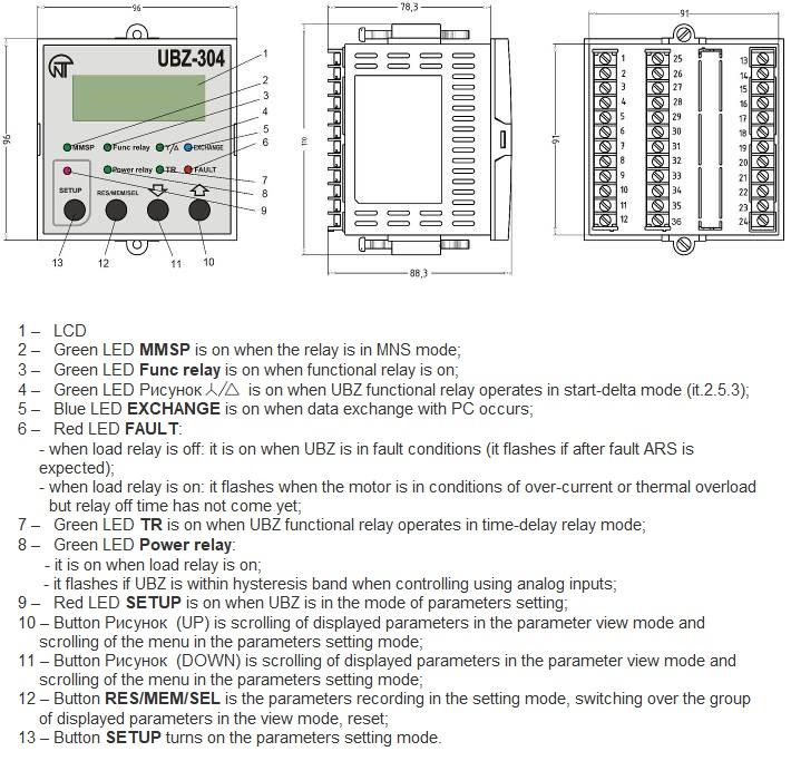
Overall dimensions (Fig.1.1), H*B*L, mm 110*96*88,3 Position in space free Housing material self-extinguishing plastic | |
Characteristics of built-in relay output contacts:
Relay | Max. current at U~250V | Number of actuations х1000 | Max. switching power | Max. continuous boosting AC / DC voltage | Max. current at Ucont=30V |
Functional relay Cos ф = 0.4 Cos ф = 1.0 |
5А 16А |
100 100 | 4000 VА | 440/300 V | 5 А |
Load relay Cos ф = 0.4 Cos ф = 1.0 |
2А 8А |
100 100 | 2000 VА | 460 V | 3 А |
Special and Service Parameters:
Measurement functions | Range | Remarks | Address |
Heat balance of the motor
| The number 1100000 corresponds to 100% of accumulated heat at which the motor is switched off when the thermal overload protection is enabled (it 3.4.7) | Read-only parameter of RS-232, RS-485 interface | 73,74 |
Index of the last fault in the fault logbook | It varies from 0 to 49, increasing by one after recording another fault in the fault logbook. When the quantity of faults will reach 50, the count of faults will begin again from scratch. | Read-only parameter | 75 |
UBZ complies with the requirements of the following international standards:
- IEC 60947-1, Low-voltage Switchgear and Control-gear; Part 1: General Rules;
- ІEC 60947-6-2:1992, Low-voltage switchgear and control gear – Part 6-2: Multiple function equipment – Control and protective switching devices (or equipment)
- CISPR 11:2004, Industrial, scientific and medical (ISM) radio-frequency equipment – Electromagnetic disturbance characteristics – Limits and methods of measurement
- IEC 61000-4-2:2001, Electromagnetic compatibility (EMC) – Part 4-2: Testing and measurement techniques – Electrostatic discharge immunity test
Note: The product characteristics comply with both international standards and corresponding national standards.
